在本教學中,我們將學習如何無線控制我們在以前的視訊中製作的Arduino機器人車。
我將向您展示三種不同的無線控制方法,使用HC-05藍牙模組,NRF24L01收發模組和HC-12遠端無線模組,以及使用智慧手機和定制Android應用程式。
您可以觀看以下視訊或閱讀下面的書面教學瞭解更多詳情。
我已經有關於如何使用Arduino板連線和使用這些模組的教學,所以如果你需要更多的細節,你可以隨時檢查它們。
他們中的每一個的連結可以在文中找到。
使用HC-05藍牙模組的Arduino機器人車控制
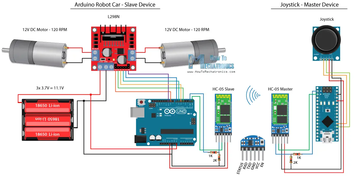
我們將從藍牙通信開始,為此,我們需要兩個需要配置為主裝置和從裝置的HC-05藍牙模組。
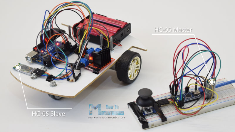
我們可以通過使用AT指令輕鬆實現,我將操縱桿設定為主人,Arduino機器人車成為奴隸。
以下是此示例的完整電路原理圖:
您可以從以下連結取得此示例所需的元件:
- HC-05 Bluetooth Module …………………………… Amazon
- Joystick Module ………………………………………… Amazon
- 18650 Batteries ………………………………………… Amazon
- L298N Driver ……………………………………………. Amazon
- 12V High Torque DC Motor ……………………….. Amazon
- Arduino Board ………………………………………….. Amazon
*請注意:這些是聯盟鏈接。 如果您通過這些鏈接購買組件,我可以進行佣金。
我將以這種方式感謝您的支持!
源代碼
我們將使用上一個教程中使用相同的代碼,我們直接使用操縱桿來控制Arduino機器人車,我們將對其進行一些修改。
HC-05主碼:
- /*
- Arduino Robot Car Wireless Control using the HC-05 Bluetooth
- == MASTER DEVICE – Joystick ==
- by Dejan Nedelkovski, www.HowToMechatronics.com
- */
- int xAxis, yAxis;
- void setup() {
- Serial.begin(38400); // Default communication rate of the Bluetooth module
- }
- void loop() {
- xAxis = analogRead(A0); // Read Joysticks X-axis
- yAxis = analogRead(A1); // Read Joysticks Y-axis
- // Send the values via the serial port to the slave HC-05 Bluetooth device
- Serial.write(xAxis/4); // Dividing by 4 for converting from 0 – 1023 to 0 – 256, (1 byte) range
- Serial.write(yAxis/4);
- delay(20);
- }
主裝置或操縱桿上的代碼非常簡單。 我們只需要讀取操縱桿的X和Y值,實際上可以調節電機的速度,並通過序列連接埠將其傳送到到從機HC-05藍牙裝置。 我們可以在這裡註意,從0到1023的操縱桿的模擬值通過將它們潛水4轉換為從0到255的值。
我們這樣做,因為從0到255的範圍可以通過藍牙裝置傳送到,在另一邊或Arduino機器人車上更容易被接受為1個位元組。
所以在這裡,如果序列接收到2個位元組,X和Y值,使用Serial.read()函數,我們將讀取它們。
- // Code from the Arduino Robot Car
- // Read the incoming data from the Joystick, or the master Bluetooth device
- while (Serial.available() >= 2) {
- x = Serial.read();
- delay(10);
- y = Serial.read();
- }
現在我們只需要將值轉換回0到1023之間的範圍,適用於下面的電機控制代碼,我們已經解釋了它在前一個視頻中的工作原理。
- // Code from the Arduino Robot Car
- // Convert back the 0 – 255 range to 0 – 1023, suitable for motor control code below
- xAxis = x*4;
- yAxis = y*4;
只需一個簡單的注意事項,當上傳代碼時,我們需要斷開Arduino板的RX和TX引腳。
完成HC-05從代碼:
- /*
- Arduino Robot Car Wireless Control using the HC-05 Bluetooth
- == SLAVE DEVICE – Arduino robot car ==
- by Dejan Nedelkovski, www.HowToMechatronics.com
- */
- #define enA 9
- #define in1 4
- #define in2 5
- #define enB 10
- #define in3 6
- #define in4 7
- int xAxis, yAxis;
- unsigned int x = 0;
- unsigned int y = 0;
- int motorSpeedA = 0;
- int motorSpeedB = 0;
- void setup() {
- pinMode(enA, OUTPUT);
- pinMode(enB, OUTPUT);
- pinMode(in1, OUTPUT);
- pinMode(in2, OUTPUT);
- pinMode(in3, OUTPUT);
- pinMode(in4, OUTPUT);
- Serial.begin(38400); // Default communication rate of the Bluetooth module
- }
- void loop() {
- // Default value – no movement when the Joystick stays in the center
- x = 510 / 4;
- y = 510 / 4;
- // Read the incoming data from the Joystick, or the master Bluetooth device
- while (Serial.available() >= 2) {
- x = Serial.read();
- delay(10);
- y = Serial.read();
- }
- delay(10);
- // Convert back the 0 – 255 range to 0 – 1023, suitable for motor control code below
- xAxis = x*4;
- yAxis = y*4;
- // Y-axis used for forward and backward control
- if (yAxis < 470) {
- // Set Motor A backward
- digitalWrite(in1, HIGH);
- digitalWrite(in2, LOW);
- // Set Motor B backward
- digitalWrite(in3, HIGH);
- digitalWrite(in4, LOW);
- // Convert the declining Y-axis readings for going backward from 470 to 0 into 0 to 255 value for the PWM signal for increasing the motor speed
- motorSpeedA = map(yAxis, 470, 0, 0, 255);
- motorSpeedB = map(yAxis, 470, 0, 0, 255);
- }
- else if (yAxis > 550) {
- // Set Motor A forward
- digitalWrite(in1, LOW);
- digitalWrite(in2, HIGH);
- // Set Motor B forward
- digitalWrite(in3, LOW);
- digitalWrite(in4, HIGH);
- // Convert the increasing Y-axis readings for going forward from 550 to 1023 into 0 to 255 value for the PWM signal for increasing the motor speed
- motorSpeedA = map(yAxis, 550, 1023, 0, 255);
- motorSpeedB = map(yAxis, 550, 1023, 0, 255);
- }
- // If joystick stays in middle the motors are not moving
- else {
- motorSpeedA = 0;
- motorSpeedB = 0;
- }
- // X-axis used for left and right control
- if (xAxis < 470) {
- // Convert the declining X-axis readings from 470 to 0 into increasing 0 to 255 value
- int xMapped = map(xAxis, 470, 0, 0, 255);
- // Move to left – decrease left motor speed, increase right motor speed
- motorSpeedA = motorSpeedA – xMapped;
- motorSpeedB = motorSpeedB + xMapped;
- // Confine the range from 0 to 255
- if (motorSpeedA < 0) {
- motorSpeedA = 0;
- }
- if (motorSpeedB > 255) {
- motorSpeedB = 255;
- }
- }
- if (xAxis > 550) {
- // Convert the increasing X-axis readings from 550 to 1023 into 0 to 255 value
- int xMapped = map(xAxis, 550, 1023, 0, 255);
- // Move right – decrease right motor speed, increase left motor speed
- motorSpeedA = motorSpeedA + xMapped;
- motorSpeedB = motorSpeedB – xMapped;
- // Confine the range from 0 to 255
- if (motorSpeedA > 255) {
- motorSpeedA = 255;
- }
- if (motorSpeedB < 0) {
- motorSpeedB = 0;
- }
- }
- // Prevent buzzing at low speeds (Adjust according to your motors. My motors couldn’t start moving if PWM value was below value of 70)
- if (motorSpeedA < 70) {
- motorSpeedA = 0;
- }
- if (motorSpeedB < 70) {
- motorSpeedB = 0;
- }
- analogWrite(enA, motorSpeedA); // Send PWM signal to motor A
- analogWrite(enB, motorSpeedB); // Send PWM signal to motor B
- }
使用智慧手機和自訂構建 Android 應用程式的 Arduino 機器人車控制
接下來,我們來看看如何使用自訂構建 Android 應用程式來控制我們的 Arduino 機器人車。
機器人車的電路原理圖與上一個例子完全相同,HC-05 藍牙模式設定為從裝置。
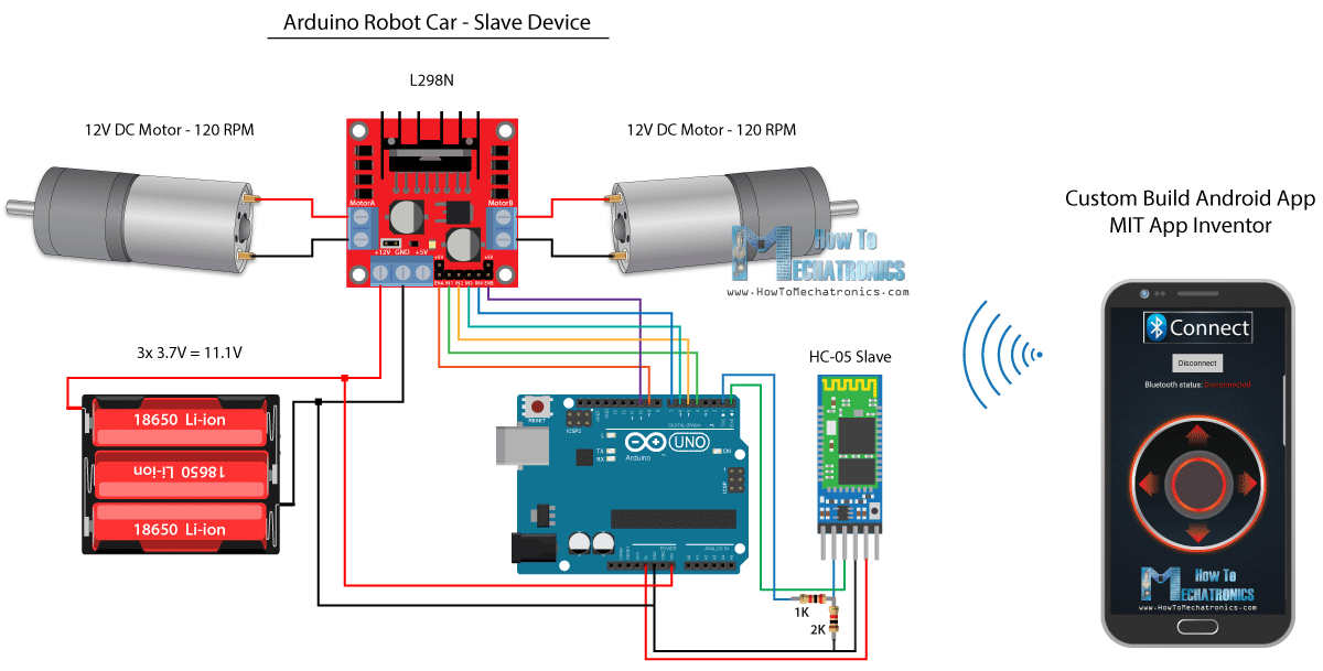
另一方面,使用麻省理工學院 App Inventor 線上應用程式,我們將構建自己的 Android 應用程式,以及它的外觀。
所以基本上應用程式模擬一個操縱桿,哪個外觀是由兩個圖像或圖像精靈組成的。
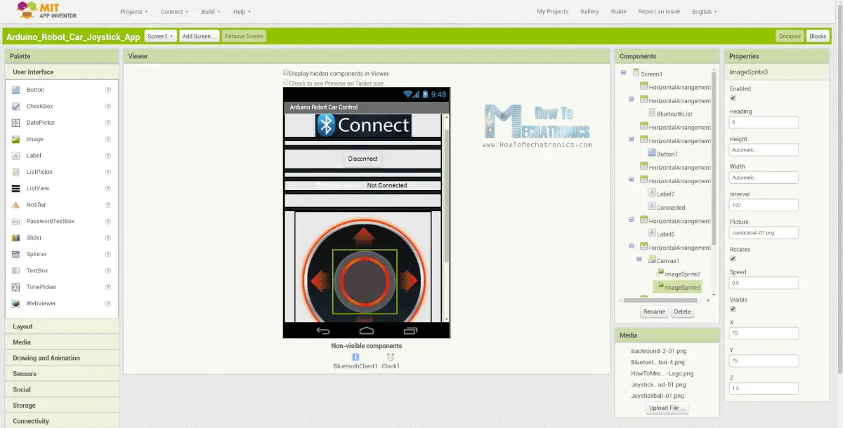
如果我們來看看這個應用程序的塊,我們可以看到當拖動操縱桿小精靈時,操縱桿球的圖像被移動到我們手指的當前位置,同時我們發送X和Y 藍牙到Arduino車的價值。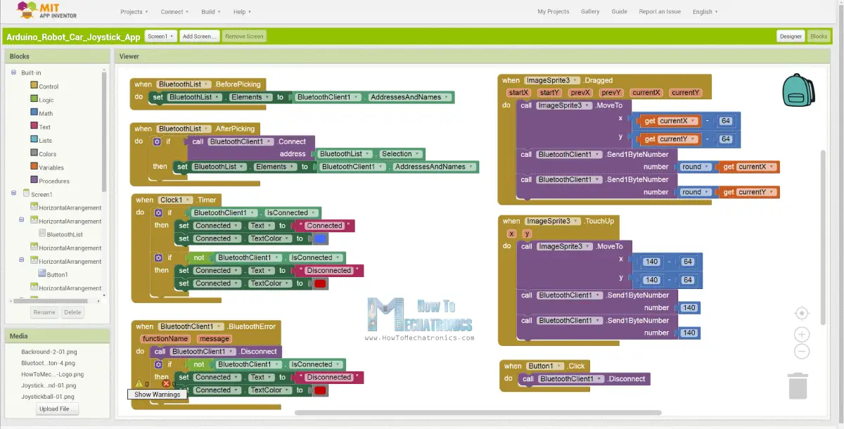
Arduino 以與上一個示例中相同的方式使用 Serial.read 函數來接受這些值。
- // Read the incoming data from the Smartphone Android App
- while (Serial.available() >= 2) {
- x = Serial.read();
- delay(10);
- y = Serial.read();
- }
我們此處需要另外做的是將接收到的X和Y值從智慧手機轉換為0到1023範圍,適用於下面的電機控制代碼。
這些值取決於畫布大小,我從我的應用程式得到的X和Y值是從60到220,使用map()函數我很容易地轉換它們。
- // Makes sure we receive corrent values
- if (x > 60 & x < 220) {
- xAxis = map(x, 220, 60, 1023, 0); // Convert the smartphone X and Y values to 0 – 1023 range, suitable motor for the motor control code below
- }
- if (y > 60 & y < 220) {
- yAxis = map(y, 220, 60, 0, 1023);
- }
在應用程式塊,我們還可以看到,當圖像精靈被觸摸時,操縱桿球移回畫布的中心,並且適當的值被傳送到到汽車以停止搬移。
您可以在網站文章中找到並下載此應用程式,以及操縱桿的兩個圖像,以便您可以自行構建或修改此應用程式。
您可以下載下面的Android應用程式,以及操縱桿的兩個圖像:
- /*
- Arduino Robot Car Wireless Control using the HC-05 Bluetooth and custom-build Android app
- == SLAVE DEVICE – Arduino robot car ==
- by Dejan Nedelkovski, www.HowToMechatronics.com
- */
- #define enA 9
- #define in1 4
- #define in2 5
- #define enB 10
- #define in3 6
- #define in4 7
- int xAxis, yAxis;
- int x = 0;
- int y = 0;
- int motorSpeedA = 0;
- int motorSpeedB = 0;
- void setup() {
- pinMode(enA, OUTPUT);
- pinMode(enB, OUTPUT);
- pinMode(in1, OUTPUT);
- pinMode(in2, OUTPUT);
- pinMode(in3, OUTPUT);
- pinMode(in4, OUTPUT);
- Serial.begin(38400); // Default communication rate of the Bluetooth module
- }
- void loop() {
- // Default value – no movement when the Joystick stays in the center
- xAxis = 510;
- yAxis = 510;
- // Read the incoming data from the Smartphone Android App
- while (Serial.available() >= 2) {
- x = Serial.read();
- delay(10);
- y = Serial.read();
- }
- delay(10);
- // Makes sure we receive corrent values
- if (x > 60 & x < 220) {
- xAxis = map(x, 220, 60, 1023, 0); // Convert the smartphone X and Y values to 0 – 1023 range, suitable motor for the motor control code below
- }
- if (y > 60 & y < 220) {
- yAxis = map(y, 220, 60, 0, 1023);
- }
- // Y-axis used for forward and backward control
- if (yAxis < 470) {
- // Set Motor A backward
- digitalWrite(in1, HIGH);
- digitalWrite(in2, LOW);
- // Set Motor B backward
- digitalWrite(in3, HIGH);
- digitalWrite(in4, LOW);
- // Convert the declining Y-axis readings for going backward from 470 to 0 into 0 to 255 value for the PWM signal for increasing the motor speed
- motorSpeedA = map(yAxis, 470, 0, 0, 255);
- motorSpeedB = map(yAxis, 470, 0, 0, 255);
- }
- else if (yAxis > 550) {
- // Set Motor A forward
- digitalWrite(in1, LOW);
- digitalWrite(in2, HIGH);
- // Set Motor B forward
- digitalWrite(in3, LOW);
- digitalWrite(in4, HIGH);
- // Convert the increasing Y-axis readings for going forward from 550 to 1023 into 0 to 255 value for the PWM signal for increasing the motor speed
- motorSpeedA = map(yAxis, 550, 1023, 0, 255);
- motorSpeedB = map(yAxis, 550, 1023, 0, 255);
- }
- // If joystick stays in middle the motors are not moving
- else {
- motorSpeedA = 0;
- motorSpeedB = 0;
- }
- // X-axis used for left and right control
- if (xAxis < 470) {
- // Convert the declining X-axis readings from 470 to 0 into increasing 0 to 255 value
- int xMapped = map(xAxis, 470, 0, 0, 255);
- // Move to left – decrease left motor speed, increase right motor speed
- motorSpeedA = motorSpeedA – xMapped;
- motorSpeedB = motorSpeedB + xMapped;
- // Confine the range from 0 to 255
- if (motorSpeedA < 0) {
- motorSpeedA = 0;
- }
- if (motorSpeedB > 255) {
- motorSpeedB = 255;
- }
- }
- if (xAxis > 550) {
- // Convert the increasing X-axis readings from 550 to 1023 into 0 to 255 value
- int xMapped = map(xAxis, 550, 1023, 0, 255);
- // Move right – decrease right motor speed, increase left motor speed
- motorSpeedA = motorSpeedA + xMapped;
- motorSpeedB = motorSpeedB – xMapped;
- // Confine the range from 0 to 255
- if (motorSpeedA > 255) {
- motorSpeedA = 255;
- }
- if (motorSpeedB < 0) {
- motorSpeedB = 0;
- }
- }
- // Prevent buzzing at low speeds (Adjust according to your motors. My motors couldn’t start moving if PWM value was below value of 70)
- if (motorSpeedA < 70) {
- motorSpeedA = 0;
- }
- if (motorSpeedB < 70) {
- motorSpeedB = 0;
- }
- analogWrite(enA, motorSpeedA); // Send PWM signal to motor A
- analogWrite(enB, motorSpeedB); // Send PWM signal to motor B
- }
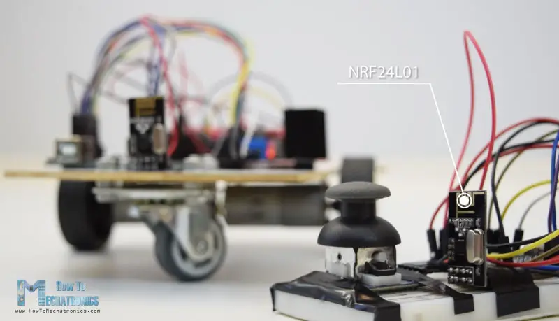
使用NRF24L01收發器模組的Arduino機器人車無線控制
現在我們可以繼續下一個方法,使用NRF24L01收發模組對Arduino機器人車進行無線控制。
這是電路原理圖。
我們可以注意到,這些模組使用SPI通信,因此與上一個示例相比,我將L298N驅動的Enable A和Enable B引腳搬移到Arduino板的2號和3號引腳。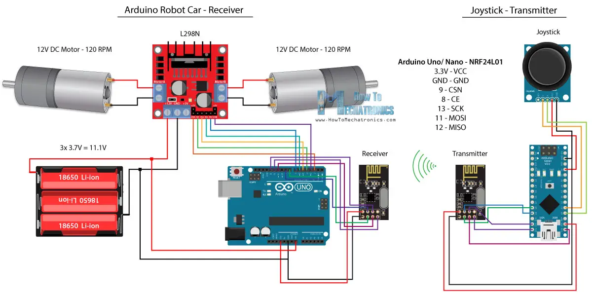
您可以在以下亞馬遜連結上獲得NRF24L01模組。
原始碼
對於這個例子,我們需要安裝RF24庫。 以與前一個例子相似的模式,在定義一些引腳並將模組設定為發射器後,我們讀取操縱桿的X和Y值,並將其傳送到到Arduino機器人車上的另一個NRF24L01模組。
首先我們可以注意到,模擬讀數是Strings,它使用string.toCharArray()函數被放入一個字元陣列中。 然後使用radio.write()函數,我們將該字元陣列資料傳送到到另一個模組。
變送器代碼:
- /*
- Arduino Robot Car Wireless Control using the NRF24L01 Transceiver module
- == Transmitter – Joystick ==
- by Dejan Nedelkovski, www.HowToMechatronics.com
- Library: TMRh20/RF24, https://github.com/tmrh20/RF24/
- */
- #include <SPI.h>
- #include <nRF24L01.h>
- #include <RF24.h>
- RF24 radio(8, 9); // CE, CSN
- const byte address[6] = “00001”;
- char xyData[32] = “”;
- String xAxis, yAxis;
- void setup() {
- Serial.begin(9600);
- radio.begin();
- radio.openWritingPipe(address);
- radio.setPALevel(RF24_PA_MIN);
- radio.stopListening();
- }
- void loop() {
- xAxis = analogRead(A0); // Read Joysticks X-axis
- yAxis = analogRead(A1); // Read Joysticks Y-axis
- // X value
- xAxis.toCharArray(xyData, 5); // Put the String (X Value) into a character array
- radio.write(&xyData, sizeof(xyData)); // Send the array data (X value) to the other NRF24L01 modile
- // Y value
- yAxis.toCharArray(xyData, 5);
- radio.write(&xyData, sizeof(xyData));
- delay(20);
- }
另一方面。
在Arduino機器人車上,在將模組定義為接收器之後,我們使用radio.read()函數接受資料。
然後使用atoi()函數,將接收到的資料,或操縱桿的X和Y值轉換為
- // Code from the Arduino Robot Car – NRF24L01 example
- if (radio.available()) { // If the NRF240L01 module received data
- radio.read(&receivedData, sizeof(receivedData)); // Read the data and put it into character array
- xAxis = atoi(&receivedData[0]); // Convert the data from the character array (received X value) into integer
- delay(10);
- radio.read(&receivedData, sizeof(receivedData));
- yAxis = atoi(&receivedData[0]);
- delay(10);
- }
這很簡單,但當然如我已經說過的,如果你需要更多的細節,如何連線和設定模組,你可以隨時檢查我的特定教學。
接收碼:
- /*
- Arduino Robot Car Wireless Control using the NRF24L01 Transceiver module
- == Receiver – Arduino robot car ==
- by Dejan Nedelkovski, www.HowToMechatronics.com
- Library: TMRh20/RF24, https://github.com/tmrh20/RF24/
- */
- #include <SPI.h>
- #include <nRF24L01.h>
- #include <RF24.h>
- #define enA 2 // Note: Pin 9 in previous video ( pin 10 is used for the SPI communication of the NRF24L01)
- #define in1 4
- #define in2 5
- #define enB 3 // Note: Pin 10 in previous video
- #define in3 6
- #define in4 7
- RF24 radio(8, 9); // CE, CSN
- const byte address[6] = “00001”;
- char receivedData[32] = “”;
- int xAxis, yAxis;
- int motorSpeedA = 0;
- int motorSpeedB = 0;
- void setup() {
- pinMode(enA, OUTPUT);
- pinMode(enB, OUTPUT);
- pinMode(in1, OUTPUT);
- pinMode(in2, OUTPUT);
- pinMode(in3, OUTPUT);
- pinMode(in4, OUTPUT);
- Serial.begin(9600);
- radio.begin();
- radio.openReadingPipe(0, address);
- radio.setPALevel(RF24_PA_MIN);
- radio.startListening();
- }
- void loop() {
- if (radio.available()) { // If the NRF240L01 module received data
- radio.read(&receivedData, sizeof(receivedData)); // Read the data and put it into character array
- xAxis = atoi(&receivedData[0]); // Convert the data from the character array (received X value) into integer
- delay(10);
- radio.read(&receivedData, sizeof(receivedData));
- yAxis = atoi(&receivedData[0]);
- delay(10);
- }
- // Y-axis used for forward and backward control
- if (yAxis < 470) {
- // Set Motor A backward
- digitalWrite(in1, HIGH);
- digitalWrite(in2, LOW);
- // Set Motor B backward
- digitalWrite(in3, HIGH);
- digitalWrite(in4, LOW);
- // Convert the declining Y-axis readings for going backward from 470 to 0 into 0 to 255 value for the PWM signal for increasing the motor speed
- motorSpeedA = map(yAxis, 470, 0, 0, 255);
- motorSpeedB = map(yAxis, 470, 0, 0, 255);
- }
- else if (yAxis > 550) {
- // Set Motor A forward
- digitalWrite(in1, LOW);
- digitalWrite(in2, HIGH);
- // Set Motor B forward
- digitalWrite(in3, LOW);
- digitalWrite(in4, HIGH);
- // Convert the increasing Y-axis readings for going forward from 550 to 1023 into 0 to 255 value for the PWM signal for increasing the motor speed
- motorSpeedA = map(yAxis, 550, 1023, 0, 255);
- motorSpeedB = map(yAxis, 550, 1023, 0, 255);
- }
- // If joystick stays in middle the motors are not moving
- else {
- motorSpeedA = 0;
- motorSpeedB = 0;
- }
- // X-axis used for left and right control
- if (xAxis < 470) {
- // Convert the declining X-axis readings from 470 to 0 into increasing 0 to 255 value
- int xMapped = map(xAxis, 470, 0, 0, 255);
- // Move to left – decrease left motor speed, increase right motor speed
- motorSpeedA = motorSpeedA – xMapped;
- motorSpeedB = motorSpeedB + xMapped;
- // Confine the range from 0 to 255
- if (motorSpeedA < 0) {
- motorSpeedA = 0;
- }
- if (motorSpeedB > 255) {
- motorSpeedB = 255;
- }
- }
- if (xAxis > 550) {
- // Convert the increasing X-axis readings from 550 to 1023 into 0 to 255 value
- int xMapped = map(xAxis, 550, 1023, 0, 255);
- // Move right – decrease right motor speed, increase left motor speed
- motorSpeedA = motorSpeedA + xMapped;
- motorSpeedB = motorSpeedB – xMapped;
- // Confine the range from 0 to 255
- if (motorSpeedA > 255) {
- motorSpeedA = 255;
- }
- if (motorSpeedB < 0) {
- motorSpeedB = 0;
- }
- }
- // Prevent buzzing at low speeds (Adjust according to your motors. My motors couldn’t start moving if PWM value was below value of 70)
- if (motorSpeedA < 70) {
- motorSpeedA = 0;
- }
- if (motorSpeedB < 70) {
- motorSpeedB = 0;
- }
- analogWrite(enA, motorSpeedA); // Send PWM signal to motor A
- analogWrite(enB, motorSpeedB); // Send PWM signal to motor B
- }
使用HC-12長距離收發器的Arduino機器人車無線控制
對於Arduino機器人車的無線控制的最後一種方法,我們將使用HC-12遠程收發器模塊。 這些模塊可以相互通信,距離可達1.8公里。
該示例的電路原理圖與HC-05藍牙模塊的電路原理圖幾乎相同,因為它們通過串行端口使用與Arduino進行通信的相同方法。
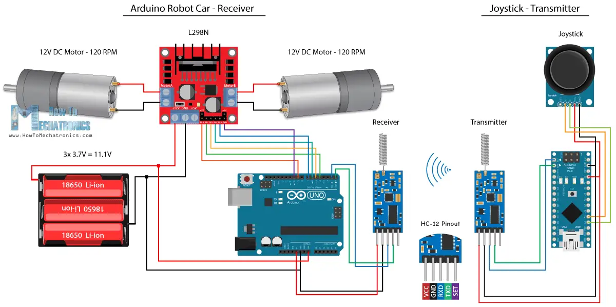
您可以在以下亞馬遜連結上取得HC-12收發器模組。
原始碼
操縱桿代碼與藍牙通信的代碼完全相同。 我們只是讀取操縱桿的模擬值,並使用Serial.write()函數將它們傳送到到另一個模組。
變送器代碼:
- /*
- Arduino Robot Car Wireless Control using the HC-12 long range wireless module
- == Transmitter – Joystick ==
- by Dejan Nedelkovski, www.HowToMechatronics.com
- */
- int xAxis, yAxis;
- void setup() {
- Serial.begin(9600); // Default communication rate of the Bluetooth module
- }
- void loop() {
- xAxis = analogRead(A0); // Read Joysticks X-axis
- yAxis = analogRead(A1); // Read Joysticks Y-axis
- // Send the values via the serial port to the slave HC-05 Bluetooth device
- Serial.write(xAxis/4); // Dividing by 4 for converting from 0 – 1023 to 0 – 256, (1 byte) range
- Serial.write(yAxis/4);
- delay(20);
- }
另一方面,使用while()迴圈,我們等待資料到達,然後使用Serial.read()函數讀取它,並將其轉換回0到1023範圍,適用於下面的電機控制代碼。
接收碼:
- /*
- Arduino Robot Car Wireless Control using the HC-12 long range wireless module
- == Receiver – Arduino robot car ==
- by Dejan Nedelkovski, www.HowToMechatronics.com
- */
- #define enA 9
- #define in1 4
- #define in2 5
- #define enB 10
- #define in3 6
- #define in4 7
- int xAxis, yAxis;
- int x = 0;
- int y = 0;
- int motorSpeedA = 0;
- int motorSpeedB = 0;
- void setup() {
- pinMode(enA, OUTPUT);
- pinMode(enB, OUTPUT);
- pinMode(in1, OUTPUT);
- pinMode(in2, OUTPUT);
- pinMode(in3, OUTPUT);
- pinMode(in4, OUTPUT);
- Serial.begin(9600); // Default communication rate of the Bluetooth module
- }
- void loop() {
- // Default value – no movement when the Joystick stays in the center
- xAxis = 510;
- yAxis = 510;
- // Read the incoming data from the
- while (Serial.available() == 0) {}
- x = Serial.read();
- delay(10);
- y = Serial.read();
- delay(10);
- // Convert back the 0 – 255 range to 0 – 1023, suitable for motor control code below
- xAxis = x * 4;
- yAxis = y * 4;
- // Y-axis used for forward and backward control
- if (yAxis < 470) {
- // Set Motor A backward
- digitalWrite(in1, HIGH);
- digitalWrite(in2, LOW);
- // Set Motor B backward
- digitalWrite(in3, HIGH);
- digitalWrite(in4, LOW);
- // Convert the declining Y-axis readings for going backward from 470 to 0 into 0 to 255 value for the PWM signal for increasing the motor speed
- motorSpeedA = map(yAxis, 470, 0, 0, 255);
- motorSpeedB = map(yAxis, 470, 0, 0, 255);
- }
- else if (yAxis > 550) {
- // Set Motor A forward
- digitalWrite(in1, LOW);
- digitalWrite(in2, HIGH);
- // Set Motor B forward
- digitalWrite(in3, LOW);
- digitalWrite(in4, HIGH);
- // Convert the increasing Y-axis readings for going forward from 550 to 1023 into 0 to 255 value for the PWM signal for increasing the motor speed
- motorSpeedA = map(yAxis, 550, 1023, 0, 255);
- motorSpeedB = map(yAxis, 550, 1023, 0, 255);
- }
- // If joystick stays in middle the motors are not moving
- else {
- motorSpeedA = 0;
- motorSpeedB = 0;
- }
- // X-axis used for left and right control
- if (xAxis < 470) {
- // Convert the declining X-axis readings from 470 to 0 into increasing 0 to 255 value
- int xMapped = map(xAxis, 470, 0, 0, 255);
- // Move to left – decrease left motor speed, increase right motor speed
- motorSpeedA = motorSpeedA – xMapped;
- motorSpeedB = motorSpeedB + xMapped;
- // Confine the range from 0 to 255
- if (motorSpeedA < 0) {
- motorSpeedA = 0;
- }
- if (motorSpeedB > 255) {
- motorSpeedB = 255;
- }
- }
- if (xAxis > 550) {
- // Convert the increasing X-axis readings from 550 to 1023 into 0 to 255 value
- int xMapped = map(xAxis, 550, 1023, 0, 255);
- // Move right – decrease right motor speed, increase left motor speed
- motorSpeedA = motorSpeedA + xMapped;
- motorSpeedB = motorSpeedB – xMapped;
- // Confine the range from 0 to 255
- if (motorSpeedA > 255) {
- motorSpeedA = 255;
- }
- if (motorSpeedB < 0) {
- motorSpeedB = 0;
- }
- }
- // Prevent buzzing at low speeds (Adjust according to your motors. My motors couldn’t start moving if PWM value was below value of 70)
- if (motorSpeedA < 70) {
- motorSpeedA = 0;
- }
- if (motorSpeedB < 70) {
- motorSpeedB = 0;
- }
- analogWrite(enA, motorSpeedA); // Send PWM signal to motor A
- analogWrite(enB, motorSpeedB); // Send PWM signal to motor B
- }
所以這幾乎是本教學的一切。
這是有趣的使用HC-05藍牙,NRF24L01和HC-12收發器模塊【Arduino機器人車載無線控制】。